- 您现在的位置:买卖IC网 > Sheet目录409 > DR-TRC105-450-EV (RFM)BOARD EVALUATION 450MHZ RFM RFIC
�� �
�
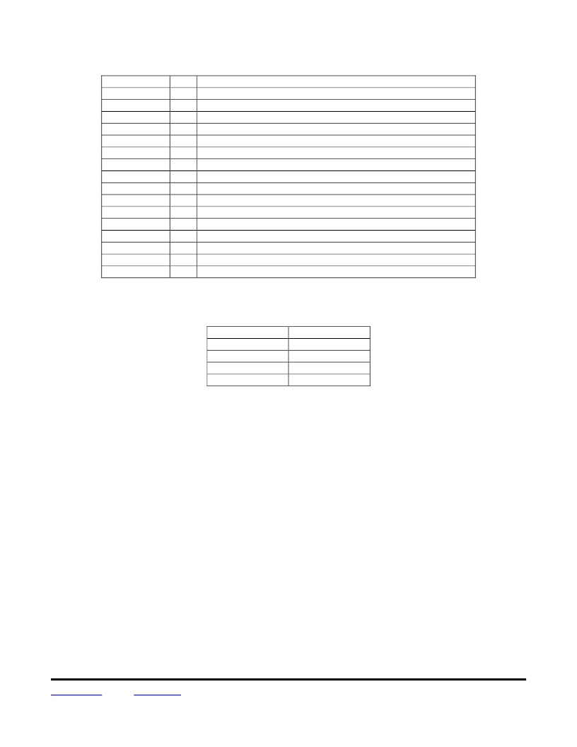
�In� addition,� IRQCFG0E� allows� several� internal� interrupts� to� be� configured.� See� Table� 79� below:�
�IRQCFG0E� bits�
�7�
�7�
�6�
�6�
�5�
�5�
�4�
�4�
�3�
�3�
�2�
�2�
�1�
�1�
�0�
�0�
�Cfg�
�0�
�1�
�0�
�1�
�0�
�1�
�0�
�1�
�0�
�1�
�1�
�0�
�1�
�0�
�1�
�0�
�Internal� Interrupt� Control�
�Start� FIFO� fill� when� start� pattern� detected�
�Control� FIFO� with� bit� 6�
�Stop� filling� FIFO� (if� bit� 7� is� 0,� this� is� start� pattern� detect)�
�Start� filling� FIFO�
�Transmitting� all� pending� bits� in� FIFO�
�All� bits� in� FIFO� transmitted�
�FIFO� OK�
�FIFO� overflow� (write� 1� to� reset� FIFO)�
�Disable� RSSI� interrupt� (bit� 2)�
�Enable� RSSI� interrupt� (bit� 2)�
�RF� signal� ≥� RSSI� threshold�
�RF� signal� <� RSSI� Threshold�
�PLL� not� locked�
�PLL� locked�
�PLL_LOCK� signal� disabled� (bit� 1� above),� Pin� 23� set� high�
�PLL_LOCK� signal� enabled�
�Table� 79�
�MCFG0C� bits� 7..6� set� the� length� of� the� FIFO� as� shown� in� Table� 80:�
�MCFG0C� bits� 7..6�
�00�
�01�
�10�
�11�
�FIFO� Length�
�16� bytes�
�32� bytes�
�48� bytes�
�64� bytes�
�Table� 80�
�The� integer� value� of� MCFG0C� bits� 5..0� plus� 1� sets� the� FIFO� interrupt� threshold.� When� receiving� in� Buffered� data�
�mode,� FIFO_Int_Rx� is� triggered� when� the� number� of� bytes� in� the� FIFO� is� equal� to� or� greater� than� the� threshold.�
�The� FIFO� threshold� facilitates� sending� and� receiving� messages� longer� than� the� chosen� FIFO� length,� by� signaling�
�when� additional� bytes� should� be� added� to� the� FIFO� during� a� packet� transmission� and� retrieved� from� the� FIFO� dur-�
�ing� a� packet� reception.� Two� additional� interrupts,� nFIFOEMPY� and� FIFOFULL� provide� signaling� that� a� packet�
�transmission� is� complete� or� a� full� packet� has� been� received� respectively.�
�The� following� is� a� typical� Buffered� data� mode� operating� scenario.� There� are� many� other� ways� to� configure� this�
�very� flexible� data� mode.�
�1.� Switch� to� standby� mode� by� setting� MCFG00� bits� 7..5� to� 001.�
�2.� Set� the� FIFO� to� a� suitable� size� for� the� application� in� MCFG0C� bits� 7..6.�
�3.� Set� the� start� pattern� length� in� RXCFG12� bits� 4..3.�
�4.� Load� the� start� pattern� in� registers� SYNCFG16� up� through� SYNCFG19� as� required.�
�5.� Set� IRQCFG0E� bit� 7� to� 0.� In� receive,� the� FIFO� will� start� filling� when� a� start� pattern� is� detected.�
�6.� Set� IRQCFG0D� bit� 7..6� to� 01.� In� receive,� IRQ0� will� flag� each� time� a� byte� is� ready� to� be� retrieved.�
�7.� Set� IRQCFG0D� bit� 5..4� to� 00.� IRQ1� signaling� will� not� be� required� in� receive� mode.�
�www.RFM.com� E-mail:� info@rfm.com�
�?� 2009-2013� by� RF� Monolithics,� Inc.�
�Technical� support� +1.800.704.6079�
�Page� 58� of� 67�
�TRC105� -� 05/29/13�
�发布紧急采购,3分钟左右您将得到回复。
相关PDF资料
DR-TXC100-433
BOARD EVALUATION 433MHZ TXC100
DR-WLS1273L-EV
KIT EVAL FOR WLS1273L
DR7000-DK
3G DEVELOPMENT KIT 433.92MHZ
DR7001-DK
3G DEVELOPMENT KIT 315 MHZ
DR7003-DK
3G DEVELOPMENT KIT 303.825 MHZ
DR8000-DK
3G DEVELOPMENT KIT 916MHZ
DR8001-DK
3G DEVELOPMENT KIT 868.35MHZ
DR8100-DK
3G DEVELOPMENT KIT 916MHZ
相关代理商/技术参数
DRTU06D06
功能描述:时间延迟和计时继电器 180-240VAC/DC 1-60VDC 6A
RoHS:否 制造商:Crydom 显示器类型:Hand Dial 电源电压:280 VAC 定时范围: 触点形式: 触点额定值:6 A 端接类型:DIN Rail
DRTU24A06
功能描述:时间延迟和计时继电器 180-240VAC/DC 24-280VAC 6A
RoHS:否 制造商:Crydom 显示器类型:Hand Dial 电源电压:280 VAC 定时范围: 触点形式: 触点额定值:6 A 端接类型:DIN Rail
DRTU24A06R
功能描述:时间延迟和计时继电器 90-140VAC/DC 24-280VAC 6A
RoHS:否 制造商:Crydom 显示器类型:Hand Dial 电源电压:280 VAC 定时范围: 触点形式: 触点额定值:6 A 端接类型:DIN Rail
DRTU24B06
功能描述:时间延迟和计时继电器 90-140VAC/DC 24-280VAC 6A
RoHS:否 制造商:Crydom 显示器类型:Hand Dial 电源电压:280 VAC 定时范围: 触点形式: 触点额定值:6 A 端接类型:DIN Rail
DRTU24B06R
功能描述:时间延迟和计时继电器 2-24VAC/DC 24-280VAC 6A
RoHS:否 制造商:Crydom 显示器类型:Hand Dial 电源电压:280 VAC 定时范围: 触点形式: 触点额定值:6 A 端接类型:DIN Rail
DRTU24D06
功能描述:时间延迟和计时继电器 12-24VAC/DC 24-280VAC 6A
RoHS:否 制造商:Crydom 显示器类型:Hand Dial 电源电压:280 VAC 定时范围: 触点形式: 触点额定值:6 A 端接类型:DIN Rail
DRTU24D06R
制造商:Crydom 功能描述:Relay; SSR; Muti Func;12-24VAC/DC; 24-280VAC ; 6A 制造商:Crydom 功能描述:RELAY SSR 6A LONG TIME DELAY 制造商:Crydom 功能描述:SSR, TIME DELAY, 6A, 280VAC, DIN RAIL; Operating Voltage Min:24VAC; Operating Voltage Max:280VAC; Control Voltage AC Min:12VAC; Control Voltage AC Max:24VAC; Control Voltage DC Max:24VDC; Timer Functions:Multifunction ;RoHS Compliant: Yes 制造商:Crydom 功能描述:DRTU24D06R/Muti Func,12-24VAC/DC, 24-280VAC 6A / ROHS: Y
DRTX06D06
制造商:CRYDOM 制造商全称:Crydom Inc., 功能描述:6 Amp AC and DC Rated output